12. Tutorial
To demonstrate the capabilities of the DDS Simulink Integration, this tutorial will create two Simulink models. One model will write DDS samples, and the second model will read the DDS samples.
Both models will be run simultaneously, and use a DDS system for communication.
A Simulink bus named ShapeType is created as part of this tutorial. The bus can be created by either using the Simulink bus editor, or by generation from an IDL file. Both options are covered in this tutorial.
12.1. Create ShapeType Bus Using Simulink Bus Editor
Buses define the data which will be published and read. Both the read and write Simulink models will make use of a bus to read and write sample data.
For this tutorial, we will create a BUS named ShapeType.
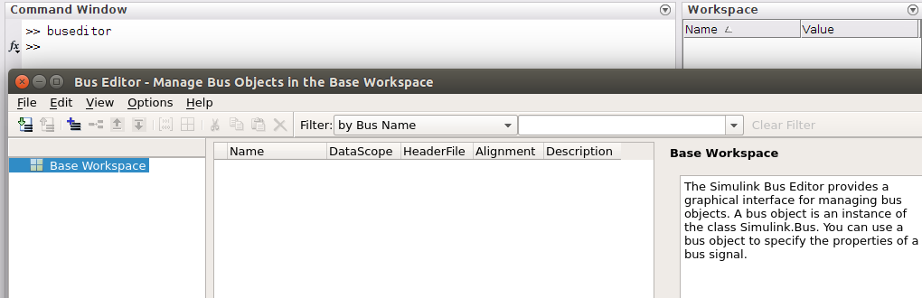
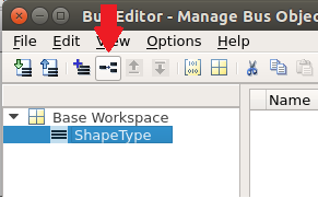
12.1.1. Open the bus editor from the MATLAB command window
12.1.2. Add a new BUS named ShapeType
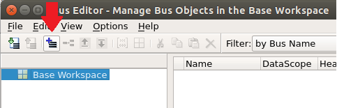
12.1.2.1. Select Add Bus button
12.1.2.2. Set Bus name and Key
Set the new bus name to: ShapeType.
Set Description to: @Key(color). This sets the Topic key.
Select Apply button to save.
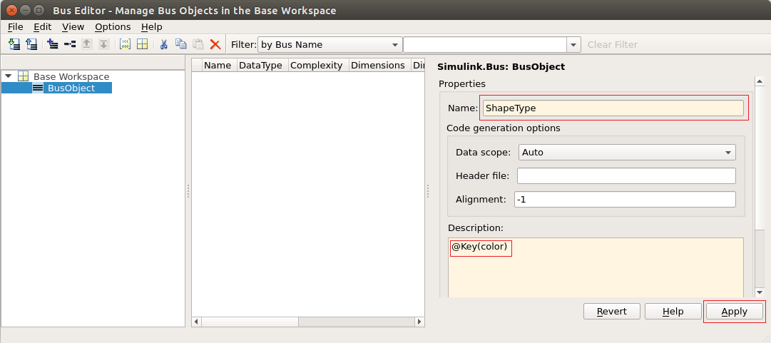
Note: If the Key is not set, the topic block’s Key annotation in the model will be shown empty and it will result in a keyless topic. Keyless topics have only one instance.
12.1.3. Add BusElements
The ShapeType bus will have 4 bus elements: color, x, y and shapesize.
A BusElement can be added to the ShapeType bus by selecting the Add/Insert BusElement button.
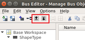
A BusElement can be moved up or down using the Move Element Up and Move Element Down buttons.
12.1.3.1. Add color
Select Add/Insert BusElement button
Set name to: color
Set DataType to: uint8
Set Dimensions to: 10
Set Description to: @String
Select Apply to save
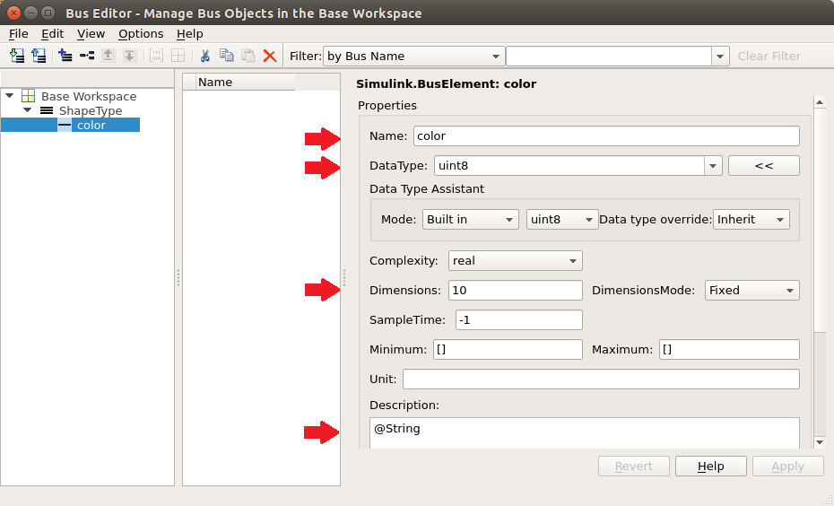
Note: This creates a DDS ‘string’ type. Bus elements of type ‘int8’ or ‘uint8’ with an annotation of @String in the Description field define a DDS string. Dimension set to 10 means Simulink is going to read only the first ten bytes of the string. You can also use the ‘@BString’ annotation to define a DDS bounded string. The dimension of the field is treated as the maximum string size.
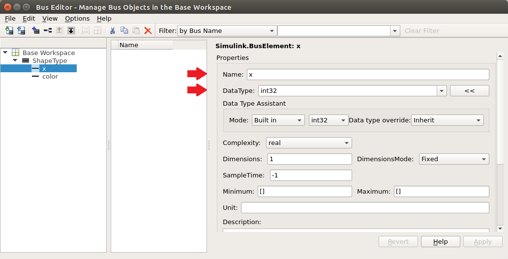
12.1.3.2. Add x
Select Add/Insert BusElement button
Set name to: x
Set DataType to: int32
Select Apply to save
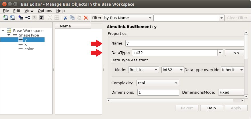
12.1.3.3. Add y
Select Add/Insert BusElement button
Set name to: y
Set DataType to: int32
Select Apply to save
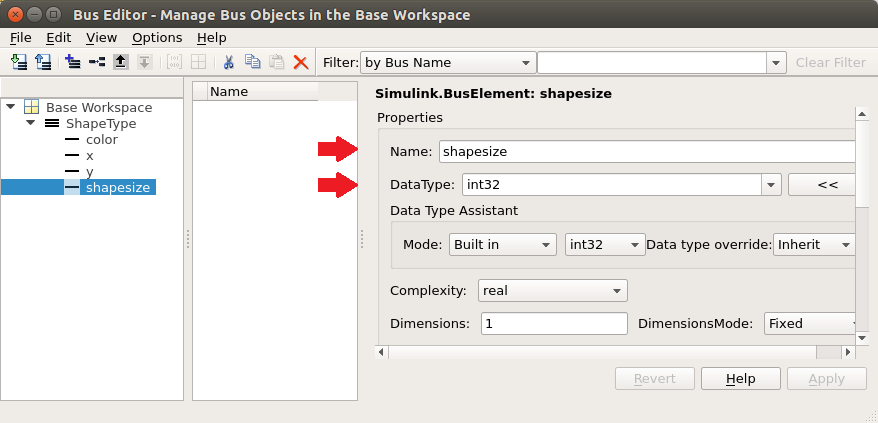
12.1.3.4. Add shapesize
Select Add/Insert BusElement button
Set name to: shapesize
Set DataType to: int32
Select Apply to save
12.1.4. Export BUS objects
When bus objects are added to the MATLAB workspace, they will be lost on MATLAB close or workspace clear. To persist the bus objects, they can be exported.
A quick way to export the ShapeType bus using the bus editor, is to right click on the bus and select Export ShapeType to File…
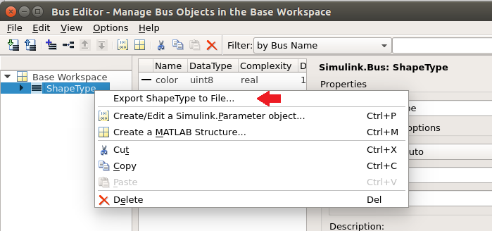
The ShapeType bus is complete.
12.2. Create ShapeType Using IDL
The public Vortex.idlImportSl function can be called to generate Simulink bus definitions from an IDL file. The generated bus definitions are inserted into the ‘Design Data’ section of a data dictionary.
- From the Simulink documentation -
“A data dictionary is a persistent repository of data that are relevant to your model. You can also use the base workspace to store design data that are used by your model during simulation.”
The data dictionary can then be referenced from your models.
12.2.1. Create IDL File
Create an IDL file to define your ShapeType topic structure. For this tutorial we will name the file ShapeType.idl.
 struct ShapeType {
   string color; //@Key
   long x;
   long y;
   long shapesize;
 };
#pragma keylist ShapeType color
IMPORTANT NOTE: The IDL file has to have a blank line after the pragma keylist declaration. (known bug)
12.2.2. Generate Simulink bus definitions from an IDL file
Steps:
In MATLAB, navigate to the directory that contains the ShapeType.idl file. Set this directory to be the MATLAB Current Folder.
Call the idlImportSl function in the MATLAB command window.
>> Vortex.idlImportSl(‘ShapeType.idl’, ‘shape.sldd’)
where:
‘ShapeType.idl’ is the name of the IDL file
‘shape.sldd’ is the name of the target data dictionary for the generated bus definitions
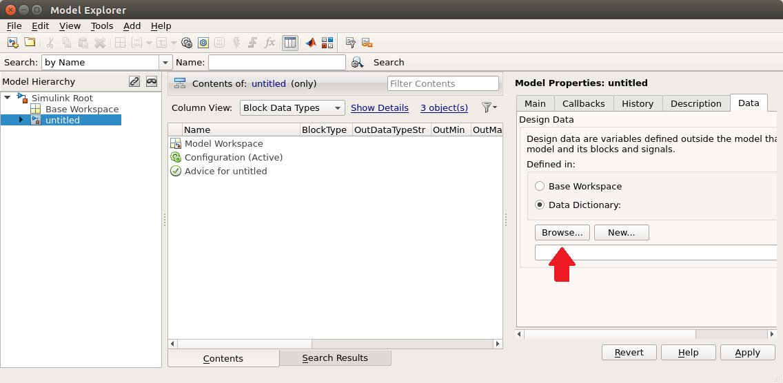
12.2.3. Model Explorer
To make use of the bus definitions generated into the data dictionary, Simulink models can specify design data using the Model Explorer.
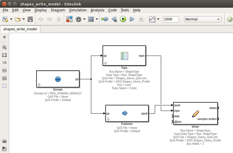
12.3. Shapes Write Model
This section outlines how to create a new DDS Simulink model that will write sample data for the topic type ShapeType.
Although not necessary, this model will use the optional Domain and Publisher blocks.
12.3.1. Create a new Simulink model
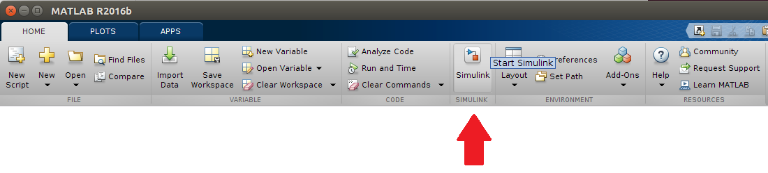
12.3.1.1. Start Simulink
12.3.1.2. Add a new blank model
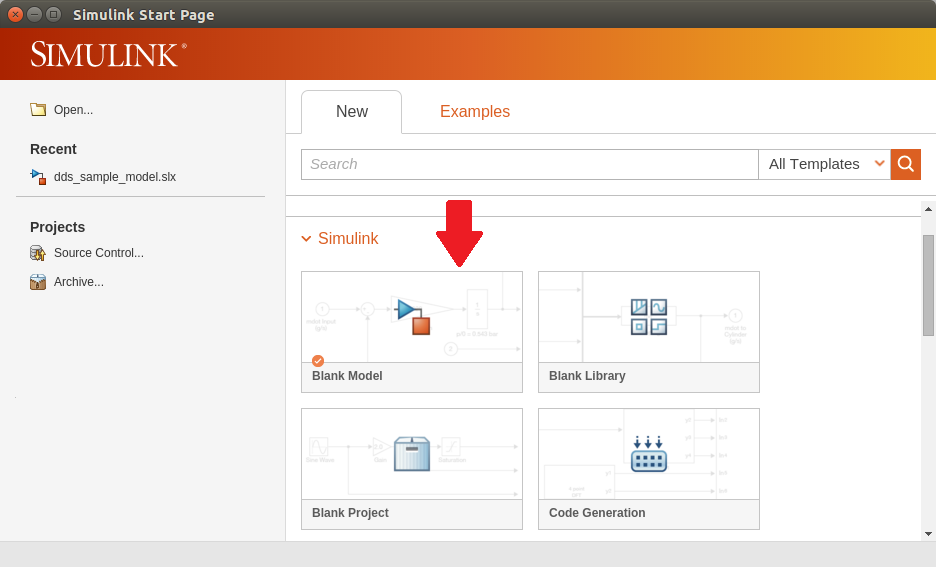
12.3.1.3. Save As…
Save the model as “shapes_write_model.slx”.
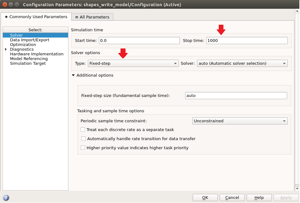
12.3.1.4. Model Settings
Open Model Configuration Parameters dialog, by selecting menu Simulation / Model Configuration Parameters.
Set the simulation stop time to 1000.0 seconds. (Note: “Simulation time is not the same as clock time. For example, running a simulation for 10 seconds usually does not take 10 seconds. Total simulation time depends on factors such as model complexity, solver step sizes, and computer speed.” Simulink Help documentation)
Set the Solver Type to Fixed-step.
12.3.2. Add Simulink DDS Blocks
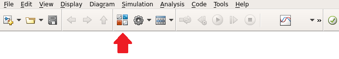
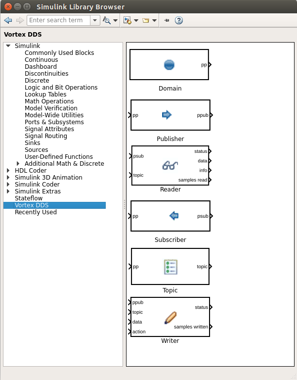
12.3.2.1. Open the Simulink Library Browser
Open the Simulink Library Browser
Browse to and select Vortex DDS to view DDS custom blocks
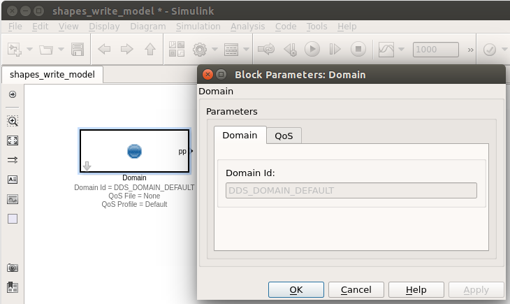
12.3.2.2. Add a Domain block
Drag a Domain participant block from the Simulink Library Browser onto the Simulink model diagram.
12.3.2.3. Set domain block properties
To set a block’s parameters, double click on the block to bring up the Block Parameters dialog.
The domain id is read only and set to DDS_DOMAIN_DEFAULT. This default is specified in the OSPL configuration file.
The QoS tab defaults to the OSPL defaults.
For this tutorial example, we are going to use the defaults, therefore no block parameters need to be specified.
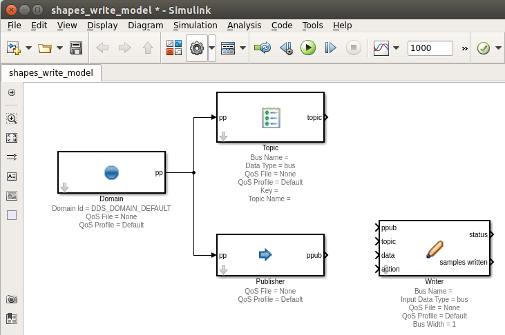
12.3.2.4. Add blocks (Topic, Publisher, and Writer)
- Using the Simulink Library Browser drag the following block types onto your diagram:
1 Topic
1 Publisher
1 Writer
12.3.2.5. Connect Domain to Topic and Publisher
Connect the Domain pp output to Topic pp input.
Connect the Domain pp output to Publisher pp input.
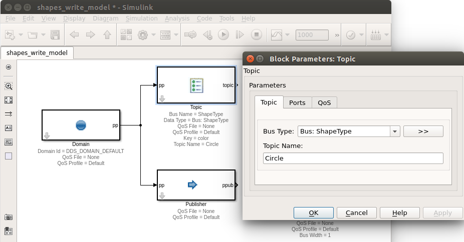
12.3.2.6. Set Topic Block Parameters
Double click on the Topic to bring up the Block Parameters dialog.
- In the Topic tab:
Set Bus Type to: ShapeType
Set Topic Name to: Circle
The Ports tab allows for the setting of optional ports. For this model, we will not change the defaults.
Select the QoS tab.
- Set the QoS file to: Shapes_Demo_QoS.xml.
- /INSTALLDIR/ADLINK/Vortex_v2/Device/VortexOpenSplice/6.8.x/HDE/x86_64.linux/tools/matlab/
/examples/simulink/dds_reader_writer_model/Shapes_Demo_QoS.xml
12.3.2.7. Connect Topic, Publisher and Writer Blocks & Set Writer Block Parameters
Connect the Topic topic output to the Writer topic input.
Connect the Publisher ppub output to the Writer ppub input.
Double click on the Writer block to edit the Block Parameters. Set the Input Data Type to the bus: ShapeType.
Select the Writer QoS tab.
Set the QoS file to: Shapes_Demo_QoS.xml.
- /INSTALLDIR/ADLINK/Vortex_v2/Device/VortexOpenSplice/6.8.x/HDE/x86_64.linux/tools/matlab/
/examples/simulink/dds_reader_writer_model/Shapes_Demo_QoS.xml
12.3.2.8. Add a Bus Creator to Set Sample Data
To generate sample data, we will add a Simulink / Signal Routing / BusCreator block to our diagram.
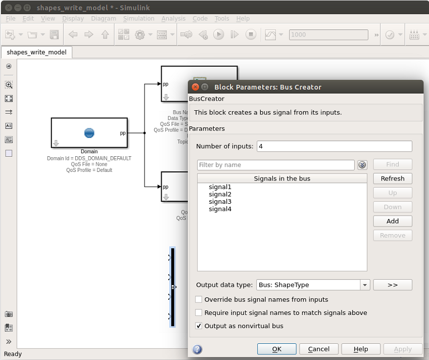
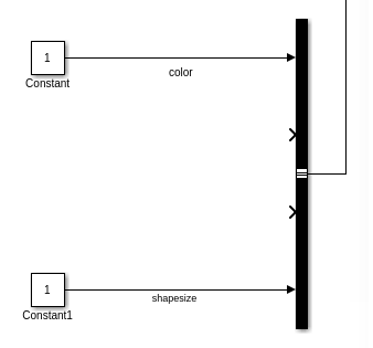
12.3.2.9. Add Bus Creator Inputs
For demonstration purposes, we will input to the BusCreator signals using Constant, Clock and Sine Wave blocks.
Note: To change the positioning of block ports, you can use the Rotate & Flip block menu item, accessible by right clicking on a block.
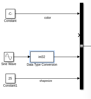
Drag 2 Simulink / Sources / Constant blocks onto the diagram
Connect one Constant block to color input signal
Connect one Constant block to shapesize input signal
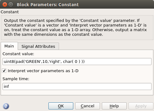
Set the Block Parameters for color signal Constant block
Set Constant value to: uint8(pad(‘GREEN’,10,’right’, char( 0 ) ))
Select OK
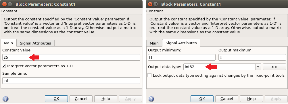
Set the Block Parameters for shapesize signal Constant block
Set Constant value to: 25
Set Output data type to: int32
Drag a Simulink / Sources / Sine Wave block onto diagram
Connect Sine Wave block to y input signal
Drag a Simulink / Signal Attributes / Data Type Conversion block onto Sine Wave connector.
Set Output data type to: int32
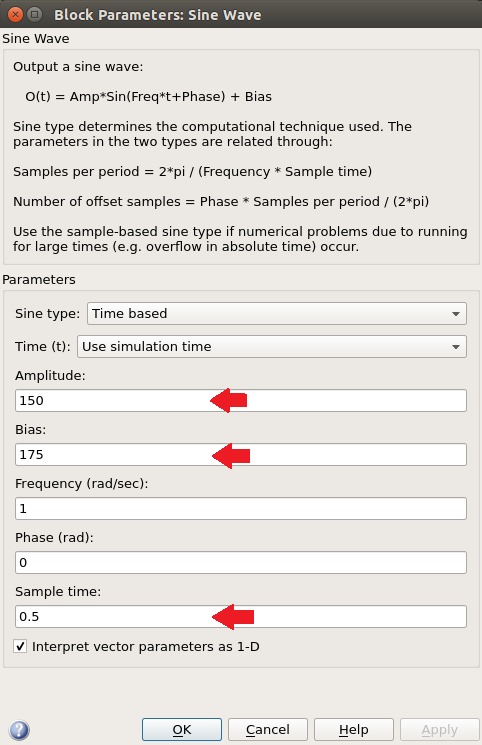
Set Block Parameters for Sine Wave block.
Set Amplitude to: 150
Set Bias to: 175
Set Sample time to: 0.5
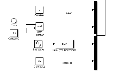
- For the x input signal, drag 3 new blocks onto diagram:
Simulink / Sources / Constant
Simulink / Sources / Clock
Simulink / Math Operations / Math Function
Set Block Parameters for Math Function block.
Set Function to: mod
Set Output signal type to: real
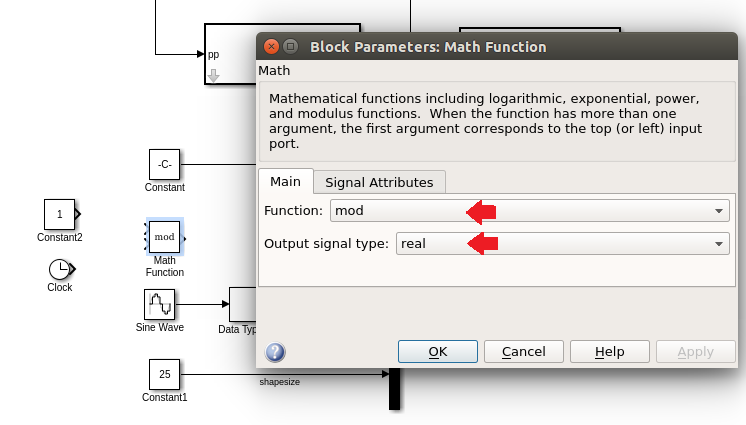
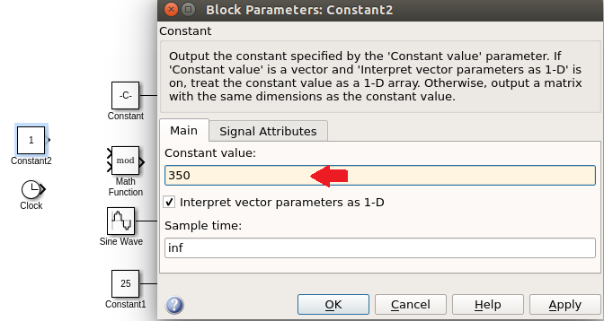
Set Block Parameters for Constant block.
Set Constant value to: 350
Connect the Clock and Constant blocks to the mod Math Function
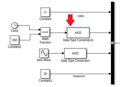
Connect the mod Math Function to the BusCreator x input signal
Drag a Simulink / Signal Attributes / Data Type Conversion block onto Math Function connector.
Set Output data type to: int32
Save your model. Your model is now complete!
12.4. Shapes Read Model
12.4.1. Create a new Simulink model
This section outlines how to create a new DDS Simulink model that will read and display sample data for the topic type ShapeType.
In this model example, we will be making use of many of the defaults, so the optional blocks will not be included in this model.
12.4.1.1. Start Simulink
12.4.1.2. Add a new blank model
12.4.1.3. Save As…
Save the model as “shapes_read_model.slx”.
12.4.1.4. Model Settings
Open Model Configuration Parameters dialog, by selecting menu Simulation / Model Configuration Parameters.
Set the simulation stop time to inf. (Note: “Specify inf to run a simulation or generated program until you explicitly pause or stop it.” Simulink Help documentation)
Set the Solver Type to Fixed-step.

12.4.2. Add Simulink DDS Blocks
12.4.2.1. Open the Simulink Library Browser
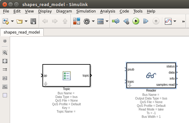
12.4.2.2. Add all required blocks (Topic and Reader)
- Using the Simulink Library Browser drag the following block types onto your diagram:
1 Topic
1 Reader
Note: For this example model, we will be using the block defaults for the Domain and Subscriber, therefore they will not be included on the model.
To set a block’s parameters, double click on the block to bring up the Block Parameters dialog.
12.4.2.3. Toggle off optional ports
Double click on the Topic to bring up the Block Parameters dialog.
In the Topic Ports tab deselect the Participant port.
Double click on the Reader to bring up the Block Parameters dialog.
In the Reader Ports tab deselect the Subscriber, Reader, Status, Info and Samples Read ports.
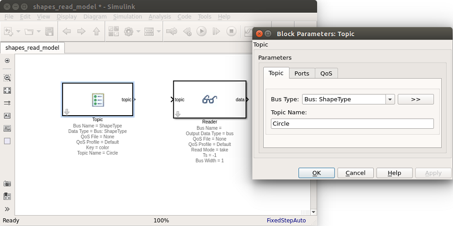
12.4.2.4. Set Topic Block Parameters
Double click on the Topic to bring up the Block Parameters dialog, select Topic tab.
- Set the Bus Type: ShapeType bus
Note: If the ShapeType bus is not displayed, select Refresh data types from dropdown list.
Set the Topic Name to: Circle.
Select the QoS tab.
- Set the QoS file toShapes_Demo_QoS.xml.
- INSTALLDIR/ADLINK/Vortex_v2/Device/VortexOpenSplice/6.8.x/HDE/x86_64.linux/tools/matlab/
examples/simulink/dds_reader_writer_model/Shapes_Demo_QoS.xml
12.4.2.5. Set Reader Block Parameters
Double click on the Reader block to edit the Block Parameters. Set the Input Data Type to the bus: ShapeType.
Select the QoS tab.
- Set the QoS file toShapes_Demo_QoS.xml.
- INSTALLDIR/ADLINK/Vortex_v2/Device/VortexOpenSplice/6.8.x/HDE/x86_64.linux/tools/matlab/
examples/simulink/dds_reader_writer_model/Shapes_Demo_QoS.xml
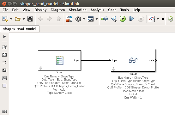
12.4.2.6. Connect Topic and Reader
Connect the Topic block topic output to the Reader block topic input.
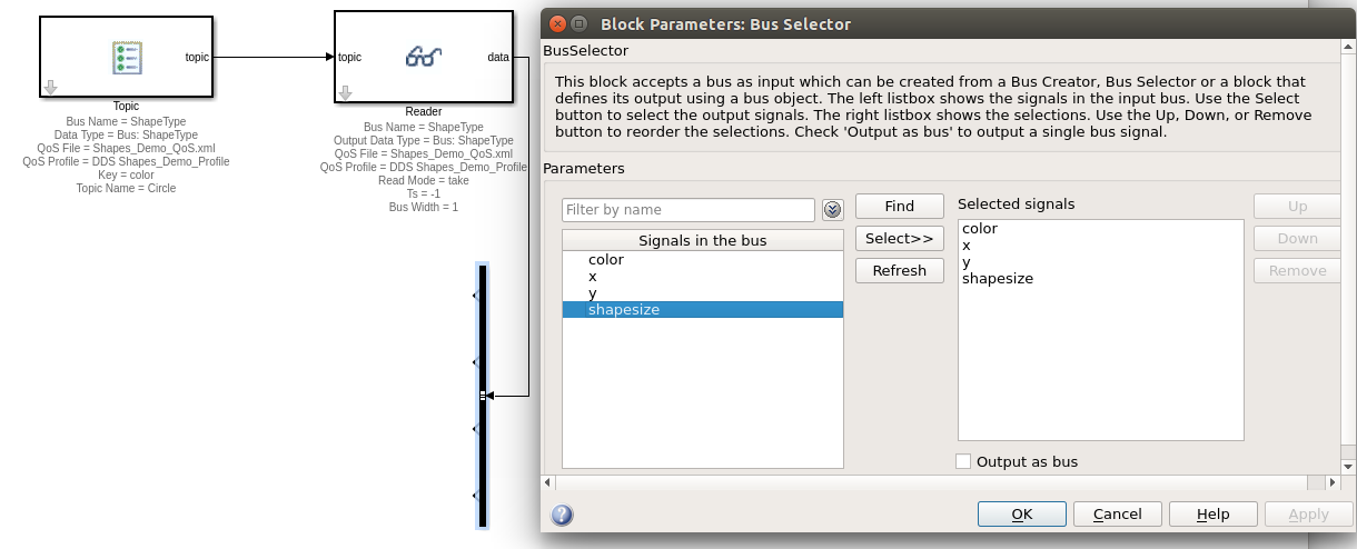
12.4.2.7. Add a Bus Selector to read and display sample data
To read and display sample data, we will add a Simulink / Signal Routing / Bus Selector block to our diagram.
12.4.2.8. Set Bus Selector Block Parameters
Specify the output signals we would like to display in our simulation. For this example, we will display all the ShapeType BUS signals in the running simulation.
Connect the Reader data output to the Bus Selector.
Double click on the Bus Selector block to edit the Block Parameters.
Add all the signals in the bus to the Selected signals.
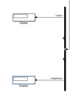
12.4.2.9. Add Bus Selector outputs
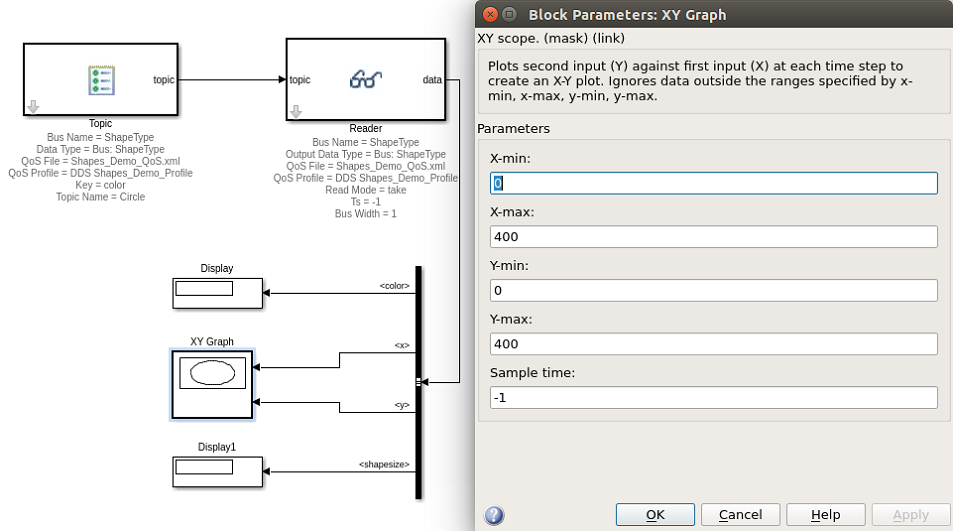
For demonstration purposes, we will output the bus signals using 2 Simulink Display blocks and an XY Graph.
Note: To change the positioning of block ports, you can use the Rotate & Flip block menu item, accessible by right clicking on a block.
Drag 2 Simulink / Sinks / Display blocks onto the diagram.
- Connect the Display blocks to the Bus Selector output signals.
Connect the Bus Selector color output signal to a Display block.
Connect the Bus Selector shapesize output signal to a Display block.
Note: Default Display block settings used.
Drag Simulink / Sinks / XY Graph block onto diagram
Connect the BusSelector x and y outputs to the XY Graph block.
- Set the Block Parameters on the XY Graph:
X-min: 0 X-max: 400 Y-min: 0 Y-max: 400
Save your model!!! The model is now complete!
12.5. Running Simulations
We now have two Simulink models. We will run both models and see that data samples are being written by one model and read be the second model.
12.5.1. Setup Write Model
Open shapes_write_model.slx.
Select menu item Simulation / Update Diagram to diagnose any possible model problems.
Fix any issues.
12.5.2. Setup Read Model
Open shapes_read_model.slx.
Select menu item Simulation / Update Diagram to diagnose any possible model problems.
Fix any issues.
12.5.3. Run Simulations
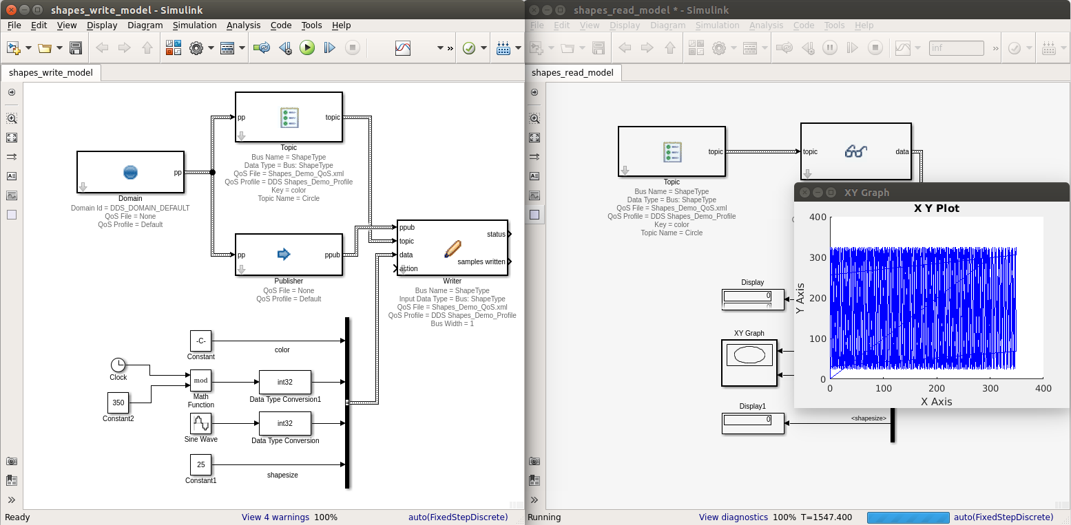
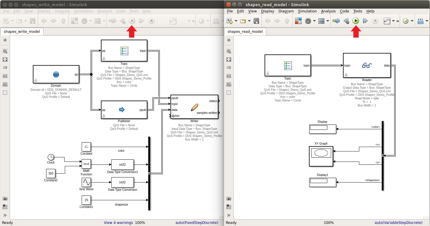
Position models side by side.
Start the read model simulation.
Start the write model simulation.
Expected: The write model will write samples, that are received by the read model and displayed in that model’s XY Graph and Display blocks.
The write model will run to completion. The read model needs to be stopped manually.
Run Results